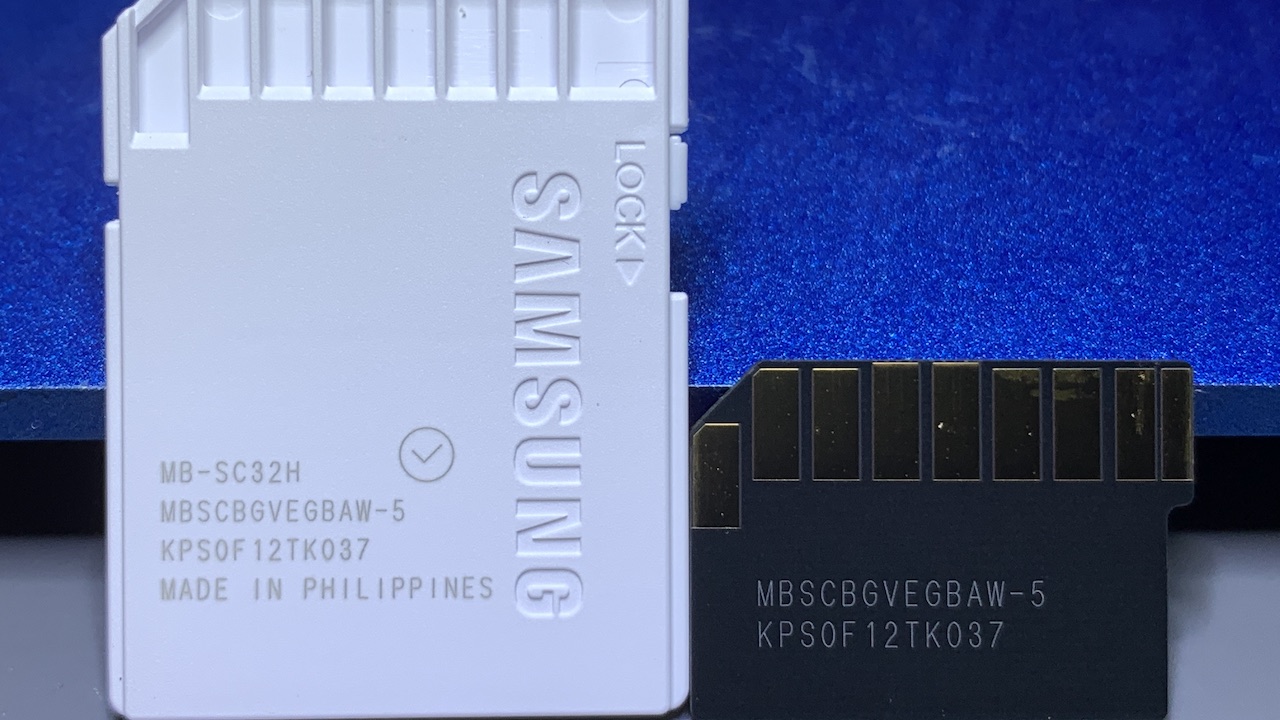
The beginning steps in preparing monolith Flash memory for data recoveries vary based on the form factor, or type of memory, used. For example, a Secure Digital (SD) monolith first requires extraction from its thin, plastic shell before it can be physically accessed for data recovery. Similarly, removal of a monolith residing in a USB Flash drive for data recovery also requires disassembly of the exterior body. On the other hand, a microSD card contains no shell or body of any type. A microSD card is a tiny monolith memory chip in card form.
Preparing a Monolith SD Card
To prepare a monolith from a SD memory card, begin by first extricating the monolith chip from its plastic case. I use a scalpel or razor blade and carefully cut around the outside edge of the case. I prefer starting to cut around a corner on the opposite side of gold interface pins to avoid damaging the monolith inside.
Next, cut into the other corner opposite the side containing the interface pins. Then, I slowly start cutting a little bit at a time from both sides towards the interface pins. Eventually the plastic case separates and the monolith chip inside will just fall out. I typically do not fully separate the top and bottom pieces of the plastic case. I avoid cutting near the monolith as much as possible and therefore only cut half to two-thirds of the way down the side of the case.
Oftentimes, I start by scoring the plastic case with a scalpel and then separate the two halves of plastic simply using a fingernail. I make every effort to exert as little force as possible when cutting the case. Then, I gently start to separate the two halves of the case away from each other. Eventually, the monolith will fall out of its case on its own due to gravity.
Sanding the Monolith Flash Memory
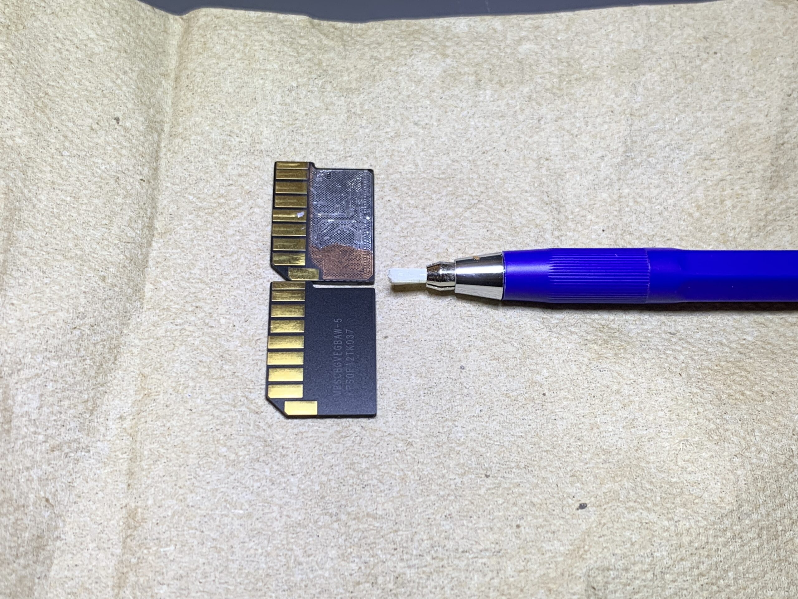
After removal from its case, place the monolith on a napkin or paper towel with the interface pins facing up. Then, while wearing gloves, use a fiberglass pen to gently remove the coating protecting the monolith’s top layer of circuitry. I recommend using a fine-tip fiberglass pen for this. The fiberglass bristles are extremely gentle so this process can take 5 or 10 minutes to complete.
Please note pieces of fiberglass constantly break off from the pen during sanding. These pieces greatly irritate skin, eyes, lungs, etc. Take care not to breathe in any fiberglass and wear gloves. Working on top of a disposable towel helps trap fiberglass pieces in the fibers of the towel, making their disposal simple, safe, and easy.
Where to Sand the Monolith
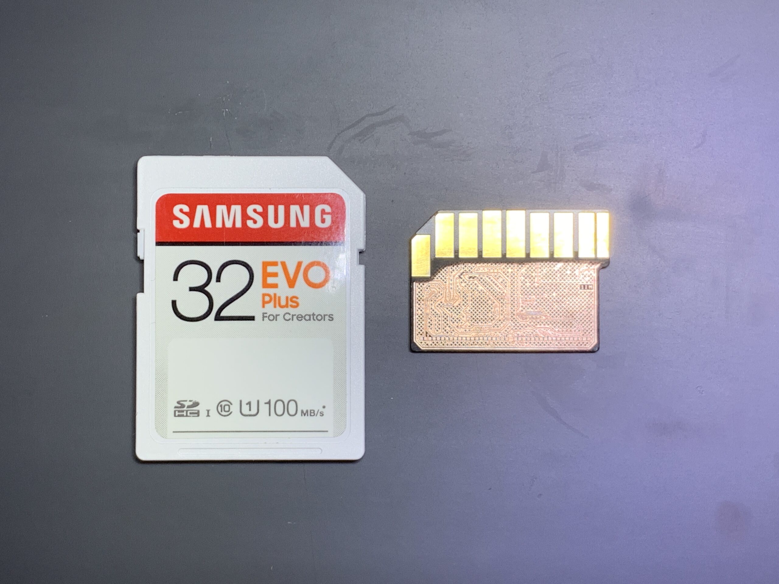
The internal circuit design of monoliths always change. Without knowing the layout of a monolith in advance, it is impossible to know what areas of the monolith require sanding down to expose the circuitry underneath. In the image above, I exposed the entire top layer of circuitry to examine the layout and design.
Soldering to the Monolith
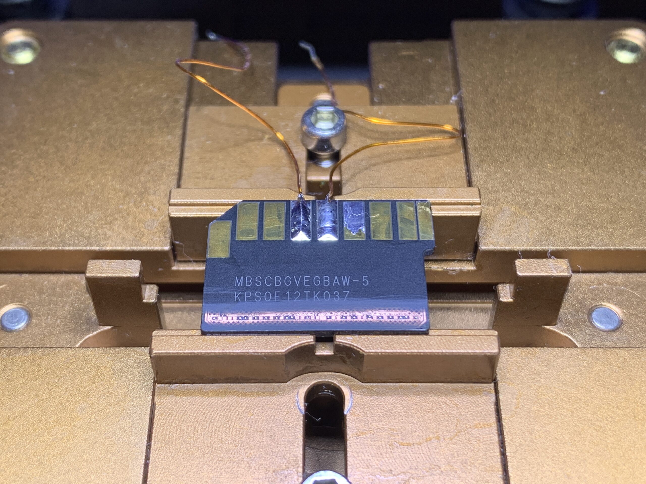
If I know the locations of the points that need electrical contacts in advance, I sand down just those areas with the fiberglass pen. In the image of the monolith above, all of the electrical contact pads reside in a single horizontal row.
Next, solder both a power and a ground wire to the monolith’s interface pins. A metal or artificial rock chip vice makes the process of soldering to a monolith easy.
Lastly, apply solder to the areas that require electrical connections. In the image above, I soldered preformed solder balls to the required pads using a hot air station. Oftentimes, in lieu of solder balls, I use a soldering iron to apply a thin layer of solder to the monolith. Be mindful not to short circuit any two or more electrically separate areas. I recommend taking a picture of the monolith before soldering to it to aid in short circuit identification.
Selecting the Best Monolith Adapter
The best adapter for recovering data from severely damaged monolith Flash memory is the ACELab PC-3000 Flash with its Spider Board Adapter. This kit bypasses the monolith’s built-in controller completely and accesses the memory core directly.
Firstly, mount the monolith in the center of the Spider Board. Prevent the monolith from moving with the application of tape. I exclusively use Kapton tape made of polyimide for this purpose. Kapton tape is translucent, electrically non-conductive, removes easily, is inexpensive, and widely available. Next, connect the power (V2) and ground wires to their respective Spider Board Adapter ports.

Placing Needles On the Monolith
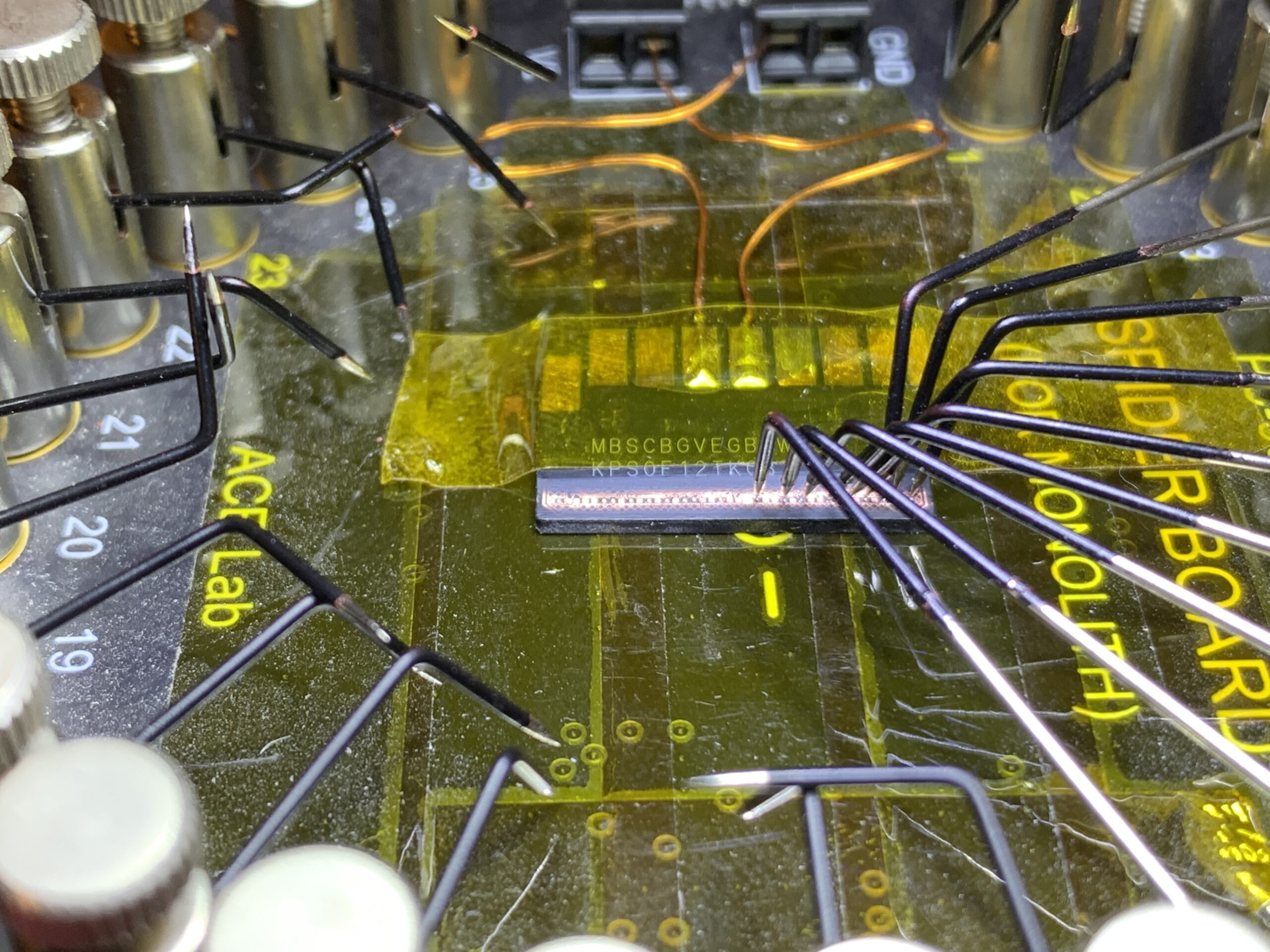
I recommend placing the needles closest to the power and ground ports first. Specifically, Needles 1, 2, 3, 23, 24, and 25. Then, place the next closest needles and work your way around. The needles rest most firmly if they come straight down and not at an angle. The needle tips also make indentations into the solder, helping the needles stay in place. Without solder, the needles slide more frequently out of place, requiring replacement.
Checking Connections to the Monolith
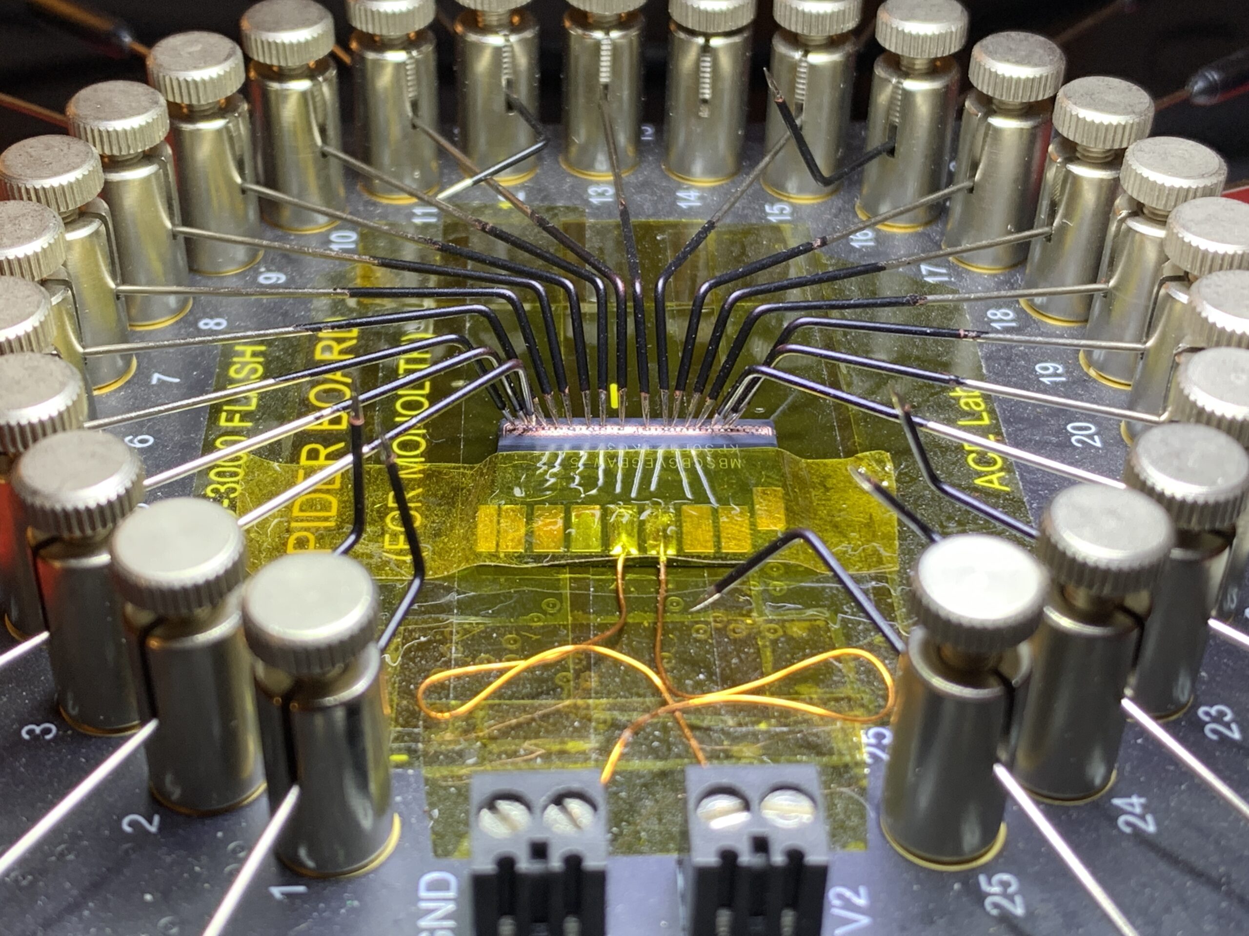
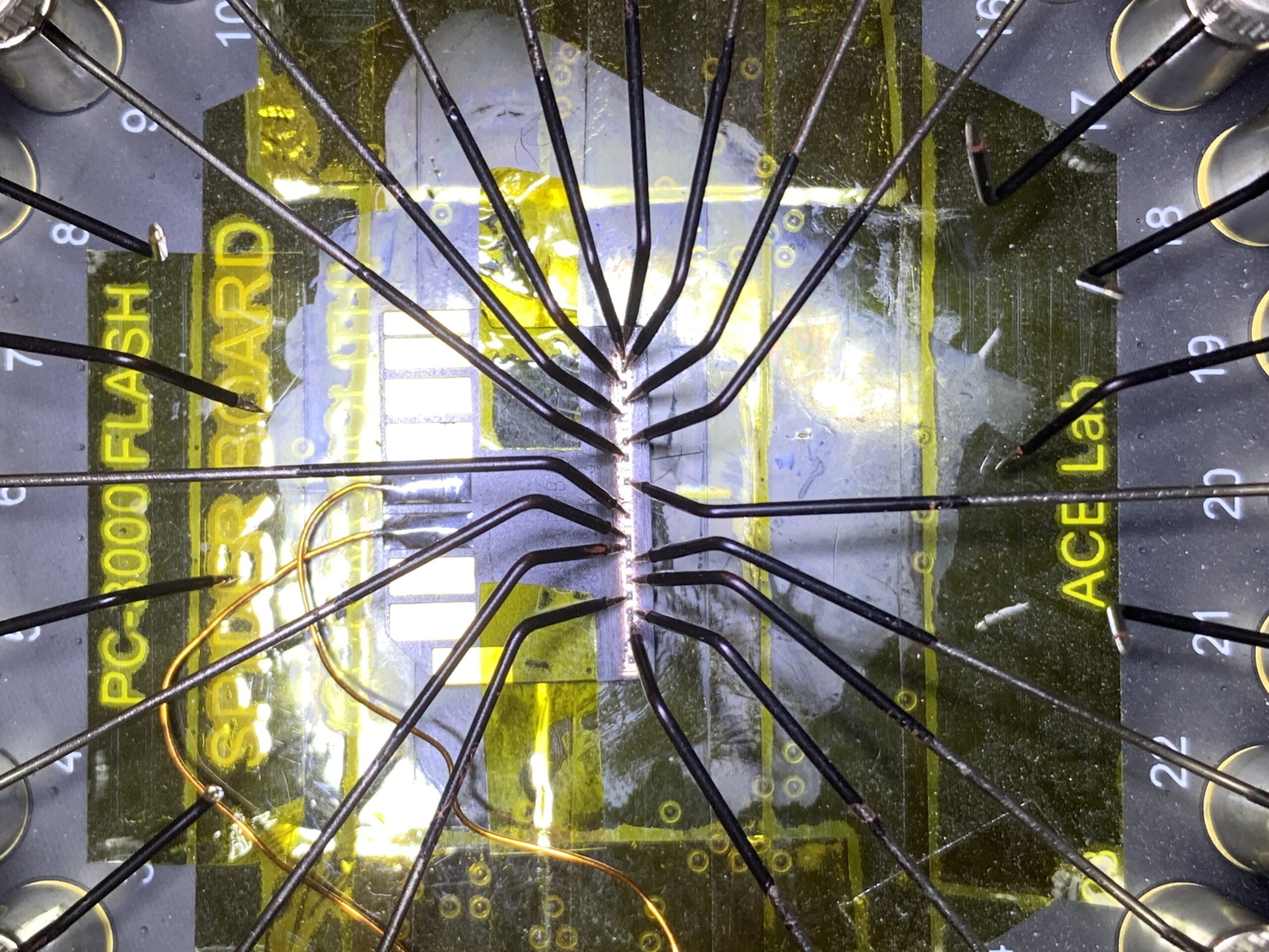
Because Spider Board needles are held in place with pressure alone, double-check the placement of the needles before attempting to initialize the memory chip. Owning a fully-articulating microscope is also highly recommended for this process.
In my case, the PC-3000 Flash features over-current short circuit protection built-in so there is no risk of damage to the Spider Board, power adapter, or computer. Nevertheless, double-checking everything before the application of power is always a smart practice to implement.
Learning the Identity of Monolith Connections
One of the more difficult skills in preparing for monolith data recovery is learning what points on the monolith to connect to. There are 3 ways to learn the identify of the pads available on the surface-level of circuitry.
Firstly, companies such as ACELabs maintain monolith chip databases containing pin-out maps and known solutions. However, due to plethora of monolith designs, it is impossible to rely 100% of the time on these databases to contain information on any specific design.
Secondly, the Spider Board Adapter features a Pinout Auto-Detection feature that determines the identity of the probe points the needles contact. While this feature works much of the time, it does not work all of the time.
Lastly, digital logic analyzers are often used to sample and then identity the monolith’s control and data lines. This method takes much more time to complete than the Spider Board’s Pinout Auto-Detection. Digital logic analyzers are built into mixed signal oscilloscopes. They also exist as standalone devices. I own a DreamSourceLab DSLogic U3Pro16, a 16-Channel USB-based logic analyzer. Any logic analyzer used needs a minimum 200MHz sample rate. The U3Pro16 samples data at a maximum of 1GHz.
Recommendations
Firstly, if a monolith Flash card or drive is not recognized with data recovery software and a USB Stabilizer, or if enough cannot data be recovered, the best solution is a PC-3000 Flash. The PC-3000 recovers data directly from the memory core, completely bypassing the controller and standard interface.
Secondly, a fiberglass pen is the best cost-effective method for exposing the top layer of monolith circuitry. Appropriate grit sandpaper, maybe 2,000 grit, also works. Expensive laser systems for removing smartphone back-glass are also used to vaporize the protective coating and expose the monolith’s circuitry.
Lastly, a data recovery hardware-software system is used to acquire a chip ID and recover data. My favorite platform for recovering data from severely damaged monolith Flash memory cards and drives is the PC-3000 Flash.
IT-SD Related Articles
