The ACELab PC-3000 Flash with Spider Board Adapter is the best kit in the world today for extracting data from damaged and non-functional Flash memory devices. Engineered to reduce signal noise and increase signal stability, the Spider Board Adapter uses metal needles held in place with mild pressure in lieu of soldering micro jumper wires.
The PC-3000 Flash Spider Board Adapter consists of a ring of 25 needles surrounding a flat stage. Needles are placed one at a time, intersecting with the circuitry available on the outside most layer of memory. As the needles can be dynamically assigned and placed anywhere across the adapter, all types of Flash monolith memory can be used with the adapter.
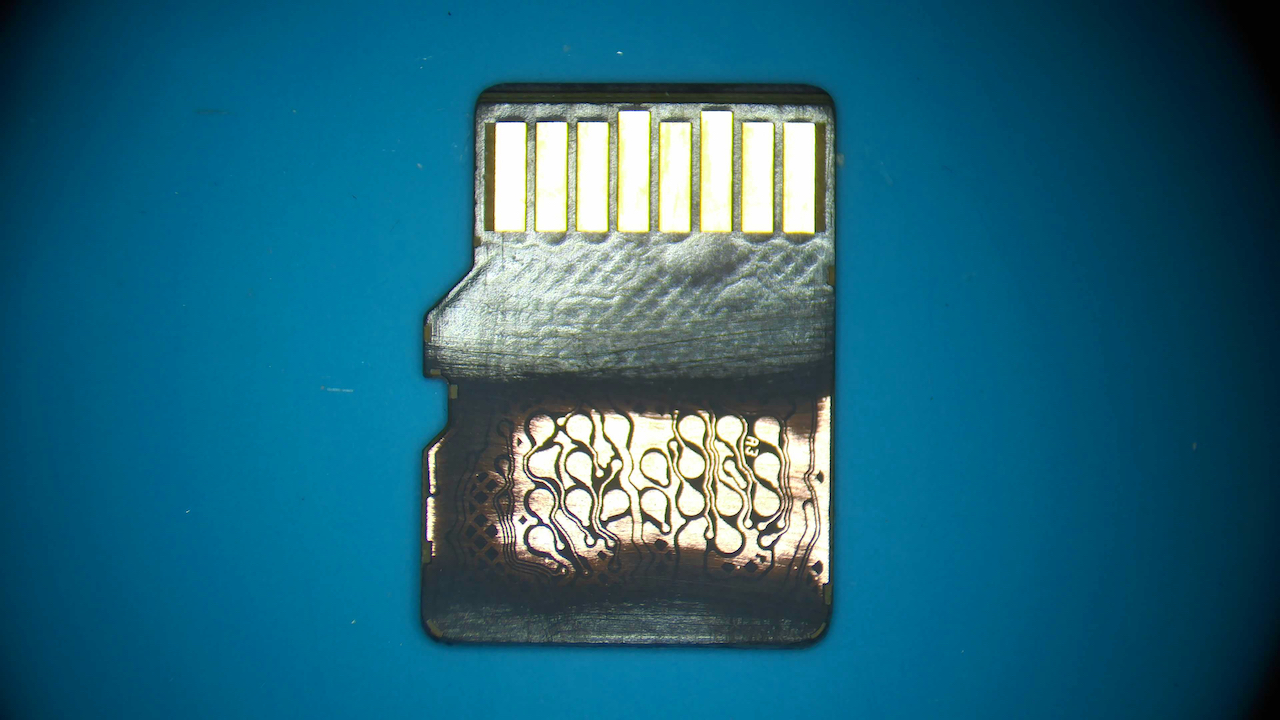
Sand the Monolith Memory Card
The first step in using the PC-3000 Flash Spider Board Adapter is to remove the coating from the underside of the memory card. This exposes the topmost layer of circuitry which extends into the Flash memory core itself. Most Flash memory utilize 8 data lines, a minimum of 6 control lines, one line for power, and more for ground.
The best tool for removing the protective coating is a fine-tip fiberglass pen. It is both inexpensive to purchase and easy to use. The process takes between 10 to 20 minutes to complete and the soft fiberglass bristles do not damage the exposed copper traces.
For a more detailed explanation of this process, please read the articles How to Sand Monolithic Flash Memory and Preparing Monolith Flash Memory for Recovery.
Add Solder to the Memory Card
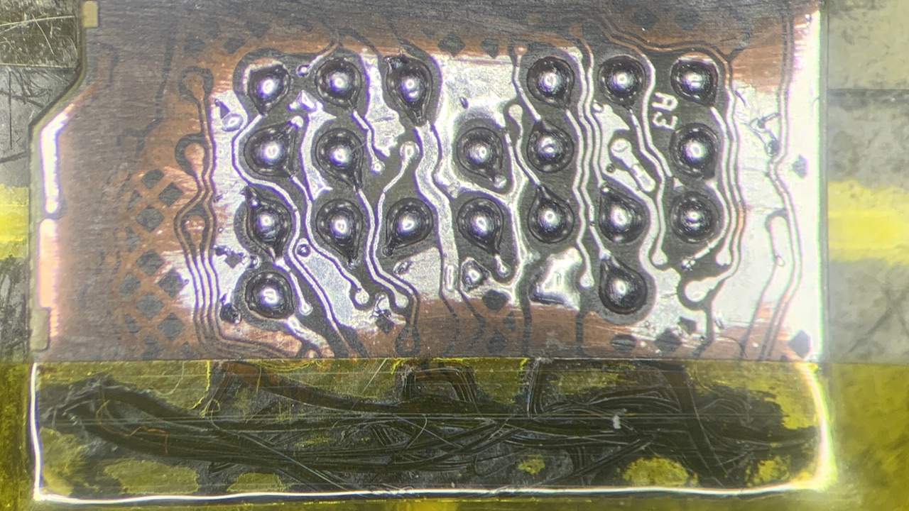
While not required, adding solder to the recently exposed copper surface layer has many benefits. First, copper oxidizes quickly, resulting in corrosion damage and poor electrical signal propagation. Adding solder prevents the copper underneath from oxidizing at all.
Second, the spider board adapter’s needles are very sharp and can also damage the exposed copper. Adding solder helps prevent physical damage from occurring.
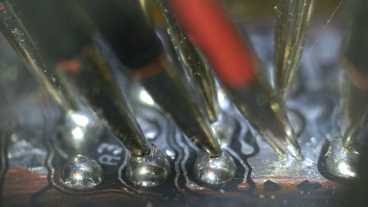
Third, the exposed copper is both flat and smooth, allowing the needles to skip and slide out of position once placed. The addition of solder provides material for the spider board needles to stick into, helping them to lock securely into position.
To apply solder to the surface of a Flash memory device, first coat the surface with a thin layer of flux. I use and recommend Amtech NC-559-V2-TF tacky flux but any high-grade flux will work well.
Next use either a knife-edge or short, bent conical soldering iron tip for applying a thin layer of solder to the entire exposed surface of card. I use the lowest temperature possible for this process, typically 270°C – 300°C with 63/37 leaded solder.
Lastly, use a conical or bent conical soldering iron tip to add a hemisphere of solder to the locations the spider board needles will be placed. Soldering iron tip diameters of 0.2mm or 0.1mm work well for this application.
Place the PC-3000 Flash Spider Board Needles
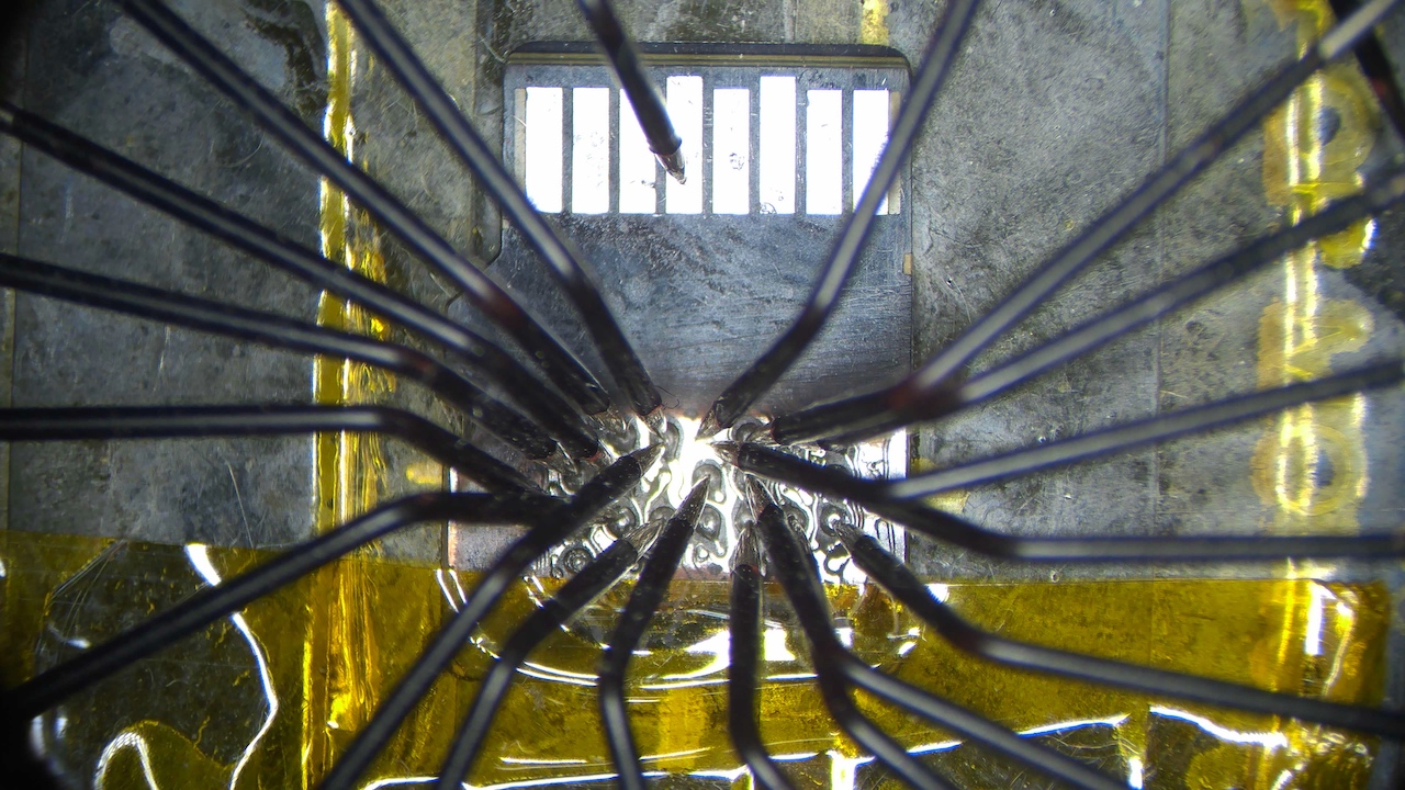
Next carefully place each required spider board needle onto its desired location on the Flash memory monolith. Secure each needle in position by turning the hand screw down into the post that holds the needle. Attempt to place each spider board needle as vertically as possible to maximize needle grip and mitigate needle skipping.
Whenever possible, use multiple needles for both power and ground connections. Two or three needles for each connection are recommended.
Advantages of Adding Solder
Adding a small hemisphere of solder to each connection area provides some material to bury the spider board needles into. Once the needles form a cavity in the solder, they tend to stay anchored in place and do not skip out of position. Another advantage is it protects the underlying copper from any physical damage caused by the needle tips.
PC-3000 Flash Spider Board Parameters
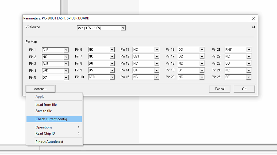
The Spider Board Parameters window controls the configuration of the Spider Board. Firstly, it features a Pinout Autodetect which can sample and automatically identify all data and control lines. Secondly, it offers a Data Line Auto-detection to determine the most probable identification of the data line.
Thirdly, it allows each needle to be manually assigned a specific a ground, power, data, or control signal. Fourthly, the Parameters window checks the current configuration to determine whether all necessary control and data lines are present. Lastly, it also checks to see if any spider board legs are touching each, causing cross-communications.
PC-3000 Flash Spider Board Chip ID
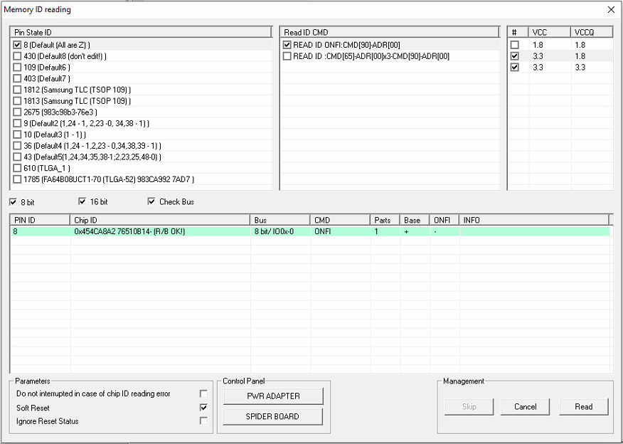
The Memory ID Reading window sets the Chip ID reading parameters. These parameters include Pin State ID, Read ID Command, and Vcc and Vccq voltages. Other settings such as Ignore Reset Status and Do Not Interrupt with ID Reading Error also reside in this window.
Recommendations
The ACELab PC-3000 Flash with the Spider Board Adapter is the best kit in the world today for extracting data from damaged and non-functional Flash memory devices. With its 25 adjustable needles, the Spider Board works with all types and configurations of monolith Flash memory. This is by far my favorite adapter for monolith NAND Flash data recovery.
IT-SD Related Articles


